Want to check how even the heating of your printer bed is, or where the heat is escaping your house, but don’t want to pay hundreds of dollars on a FLIR camera? Ever looked at your laser-guided infrared thermometer and thought to yourself, “golly, this device only has about 25% of the number of lasers I need”? Introducing Thermal Handheld Rendering meets Additional Lasers (THRmAL), an AVR-powered handheld thermal imaging device based on Panasonic’s Grid-EYE line of thermal sensors. It has a number of advantages over other thermal imaging solutions:
- 4 lasers to clearly mark the corners of the sensor’s FOV
- 64x the number of pixels found in an infrared thermometer (assuming said thermometer could be considered to have 1 pixel)
- Comfy TPE grip
- Contains an unnecessary quantity of carbon fibre
THRmAL was primarily constructed from components I already had in my parts drawer (and I expect many other makers do too), meaning the only real costs were the Grid-EYE breakout, OLED panel, and custom PCB fabrication.
Electronics
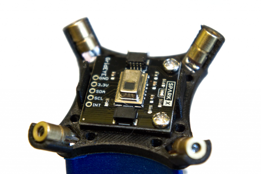
Sensor
THRmAL uses the Panasonic AMG8833 sensor mounted on Sparkfun’s Qwiic breakout board, which comes with a handy mounting holes and a 4-pin JST connector. Surrounding the Grid-EYE are 4 lasers angled to match the corners of the sensor’s 60° horizontal and vertical FOV. This way, when the lasers are powered, 4 points are projected to form a square (from the THRmAL’s perspective) on the target surface.
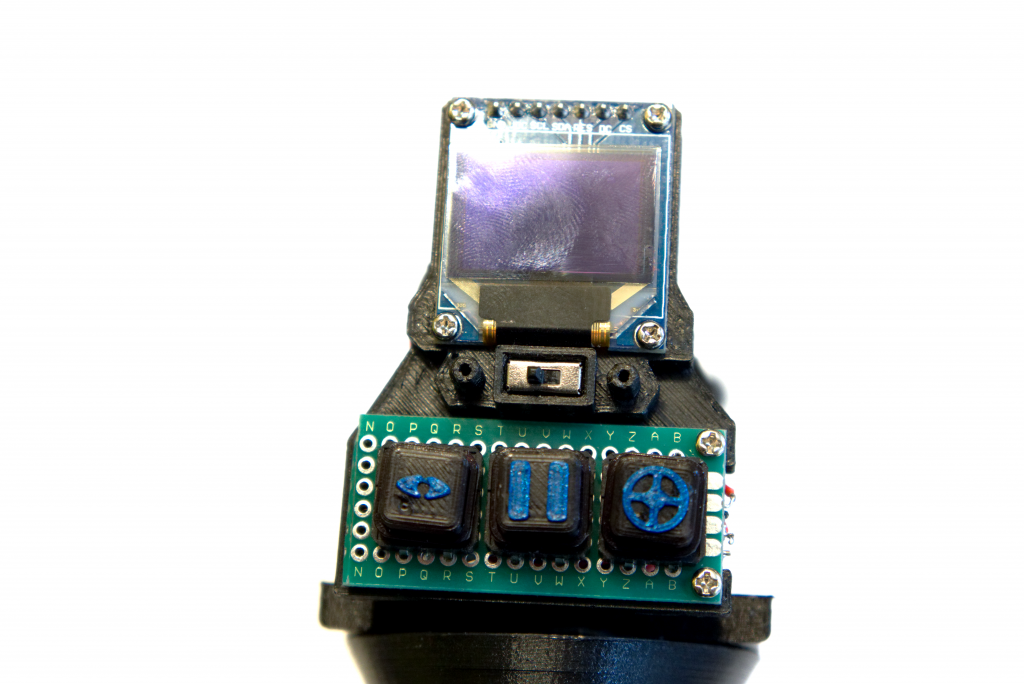
Display and Interface
The display is a SSD1331 OLED module running in SPI mode (despite the fact that the pins are labeled SDA and SCL). Below it are 3 tactile switches with custom keycaps (produced using a filament swap on the first layer of the iconography) and a power switch. Unfortunately, updating the entire display each frame means THRmAL can only achieve approximately 3 frames per second, but I did come up with a workaround for this (which I’ll explain in the Software section).
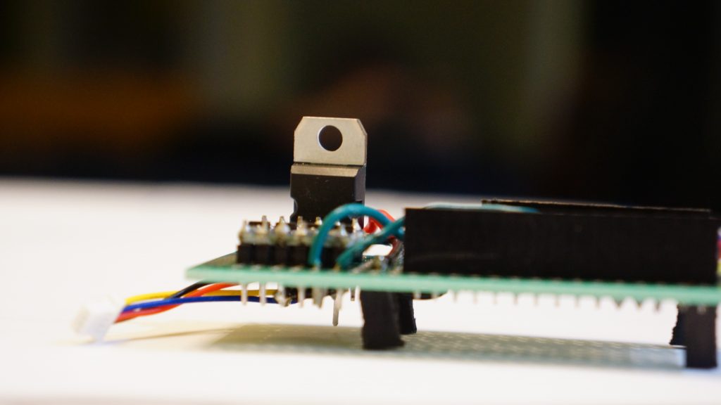
PCB
The core of almost any electronics project is a circuit board of some sort, and THRmAL is no exception. THRmAL’s PCB is home to:
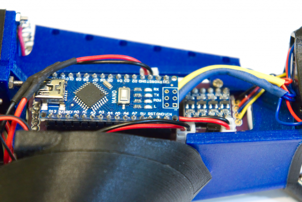
- A 5V Arduino Nano clone that I keep my parts drawer stocked with at all times (I get them in packs of 5 or 10)
- A logic level shifter to let the 5V Nano talk to the 3.3V sensor (I am wholly aware that just using a 3.3V uC would let me avoid the need for level shifting, I just didn’t have handfuls of 3.3 uCs at the time)
- A buck converter to allow for variable input voltages to be used efficiently (currently the THRmAL runs on a 9V battery)
- A slew of connectors to interface with the sensor, display, buttons, etc
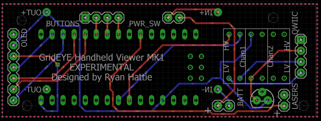
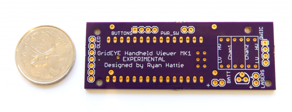
After quickly testing out the electronics on a breadboard, and later a protoboard, I drew up a PCB design in EAGLE and sent it off to OSH Park for fabrication.
A few weeks later, and I had a promptly produced perfect purple PCB, as promised.
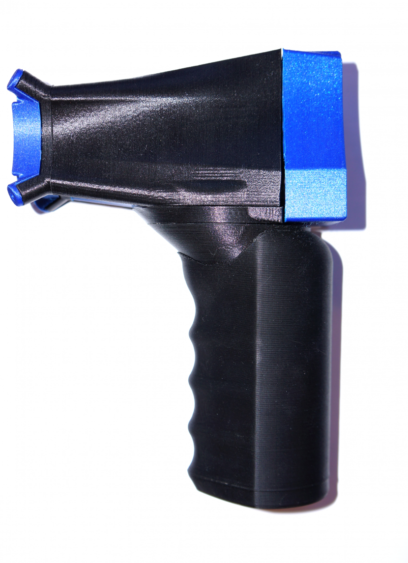
Body
The body of THRmAL is constructed from 2 main materials: Atomic Filament Carbon Fiber PETG and Proto-pasta Highfive Blue HTPLA. The contrast between the metallic flake of the Highfive Blue and the dark semi-matte surface of the carbon PETG is something not easily captured in a photo.
The exterior consists of 2 PLA faceplates and 2 PETG side panels, which are friction-fit and can easily be removed to unsocket the Nano, tune the buck converter, or simply show off the internals. Additionally, the handle is attached by sliding it onto a rail from the front, meaning that alternative handles with various battery types could be installed without tools (although I haven’t had any reason to design a handle other than the 9V battery one). There is not a single visible fastener on THRmAL when it is fully assembled.
The handle grip is made out of Spool3D 80A TPE, and feels soft and squishy in the hand.
Software
THRmAL’s software is fairly basic and slapped together, but it’s still worth mentioning. I more or less just glued the Adafruit SSD1331 library and the Sparkfun GRID-Eye library together with a simple Arduino sketch. THRmAL has a view button that lets you switch between 4 view modes:
- Red-blue fullscreen
- Greyscale fullscreen
- Red-blue mini
- Greyscale mini
The “mini” modes are half the size on each axis, meaning it only uses 1/4 of the number of pixels required for the fullscreen modes. This lets us achieve around the 10FPS of the sensor, giving a much smoother viewing experience.
The hold button simply pauses rendering, similar to how releasing the trigger of an infrared thermometer will hold the current sample. You’ll never guess what the laser button does…
Files
If you want to build your own THRmAL, I’ve posted all the project files and a build guide on Thingiverse.